The Autopsy of a Scorched Inverter: A Forensic Look at Grounding Failures
I was standing on a composite roof in the heat of July, my boots sticking to the softening tar, staring at a $4,000 hybrid inverter that had turned into a high-priced paperweight. There was no smoke left, just the lingering, sharp ozone scent of a high-energy arc and the dull, charred remains of a communication board. The homeowner was baffled; they had just had the panels installed six months prior. But when I pulled my Wiggy out and started testing the rails, the story became clear. It wasn’t a lightning strike that killed the system; it was a lack of respect for the physics of the path of least resistance. The installer had treated the grounding as an afterthought, a ‘green wire’ to satisfy the inspector, rather than a critical safety system designed to handle the massive potential difference between the sky and the soil.
My journeyman used to smack my hand if I stripped a wire with a knife. ‘You nick the copper, you create a hot spot,’ he’d scream. He was right. In the world of solar, those hot spots aren’t just at the wire ends; they exist at every rail junction, every mid-clamp, and every lug that isn’t properly torqued to mitigate the inevitable Cold Creep of the aluminum racking. If you don’t account for the thermal expansion and the oxidation layers on those rails, you aren’t building a power plant; you’re building a fire hazard.
The Physics of the Path: Why Your Solar Array is a Lightning Magnet
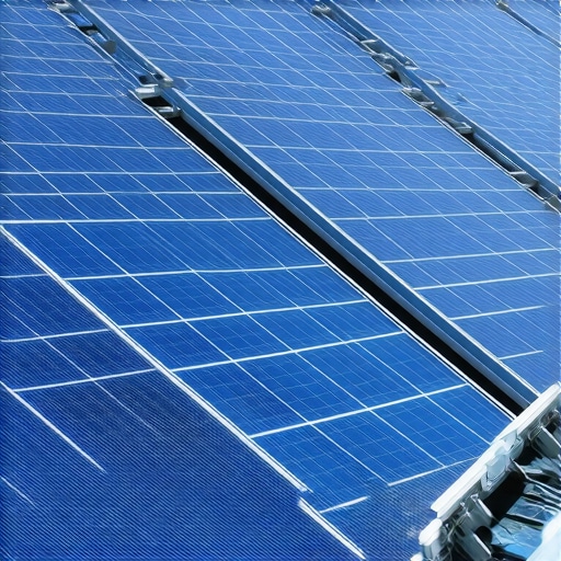
When we talk about a solar panel electrical hookup, most people focus on the DC strings and the AC output. But the grounding system is the most complex ‘circuit’ in the house. You have two distinct jobs: equipment grounding (bonding) and system grounding. On a roof, you have miles of anodized aluminum rail. Anodization is an insulator. If you just screw a lug into an anodized rail without using a WEEB (Washer, Electrical Equipment Bond) or a specialized lug that pierces that coating, you have no ground. You have a series of isolated metal islands waiting for a static charge or a surge to jump the gap.
“Aluminum wire connections can overheat and cause a fire without tripping the circuit breaker.” – CPSC Safety Alert 516
This is where electrical load calculations become secondary to bonding integrity. If a fault occurs on the roof—perhaps a squirrel chews through a Romex line or a DC lead—the entire racking system can become energized. Without a solid, low-impedance path back to the main panel, the breakers won’t trip. The metal stays live, the heat builds up, and eventually, the shingles ignite. This is why NEC code updates have become so obsessive about ‘continuous’ grounding paths.
Component Zooming: The Micro-Physics of Galvanic Corrosion
Let’s talk about why your ground fails five years after the install. It’s called galvanic reaction. You have a copper ground wire (the standard for electrical wiring services) being clamped to an aluminum rail. In the presence of moisture, these two metals trade electrons, creating a layer of non-conductive oxidation. This is the silent killer. I’ve seen ‘tight’ lugs that had 500 ohms of resistance because the installer didn’t use a stainless steel star washer or an anti-oxidation compound like Monkey Shit (duct seal) to keep the elements out of the connection. When I do a forensic inspection for insurance claim electrical work, this is the first thing I check. I use my Tick Tracer to see if the racking is floating at a different potential than the grounded conductor. If it is, the system is a ticking bomb.
The Integrated System: From Roof to Trench
A proper solar install doesn’t end at the eaves. It involves the entire infrastructure. Often, this requires trenching electrical conduit to a ground rod array that is separate from, but bonded to, the main house ground. If you’re running a ground-mount system or a large residential array, you have to ensure that the earth’s resistance is low enough to actually draw current. If you’re also ensuring safe and efficient EV charging station setup at home, your total household load and grounding system are under more stress than ever before. You cannot just slap a new breaker in and hope for the best. A circuit breaker replacement is useless if the bus bar it’s drawing from is already over-saturated by solar back-feed and a Level 2 charger pulling 40 amps.
I’ve seen panels where the network cable installation for the solar monitoring was run right next to the high-voltage DC lines. In a surge event, the lack of shielding and proper grounding meant the surge traveled through the Cat6 and fried the homeowner’s router, their TV, and their smart fridge. It’s all connected. You can’t treat parking lot lighting or emergency exit lighting with one set of rules and solar with another. The electrons don’t care about the application; they only care about the voltage drop.
The Fix: Sleep Better Through the Storm
To do it right, you start with a Rough-in that respects the code. Every rail segment must be bonded. You use lay-in lugs that are UL-listed for the specific racking brand. You run a #6 AWG bare copper wire—the Home Run of safety—from the roof all the way to the Grounding Electrode System. You don’t ‘daisy chain’ with thin wire. You use your Dikes to clean up every termination, ensuring no strands are splayed. If you’re unsure about your current setup, especially if you’re experiencing ev-charger troubleshooting or flickering lights, it’s time for a professional review. Don’t wait for the fishy smell of melting plastic. Contact the experts at Reliable Electric Pro to get a real forensic look at your system before the next storm hits. Electricity isn’t a hobby; it’s a force of nature that requires a 35-year veteran’s respect for the ‘Wiggy’ and the code book.